All about Tubes, Tube Circuits, Tube Gear
Showing posts with label RIAA. Show all posts

Monday, June 25, 2012

RIAA Preamp (part 6):

Here are the last useful RIAA EQs:


(G) Columbia 78 rpm


 (F) RCA 78 rpm

(H):  Decca FFRR
 

 Note that with the last (Decca FFRR), only the lower left cap is the same, and this is best made up as a separate network.


Sunday, June 24, 2012

RIAA Preamp Build (part 5): Extras

Now lets take the basic RIAA (Flat Xover),
and form two more of the most popular EQs:

(D)  The NARTB Standard:  (Artist, Capitol, M.G.M., and many other American pressings) = (C) The 500 Hz Flat Xover + a cap:


and finally,

(E)  The Columbia Microgroove:  (NARTB + a resistor):

We can also squeeze out the RCA Victor 78 rpm EQ from a basic RIAA (flat 500), by adding an additional L-network, but after this we have to start from scratch to punch out the last two, (Decca FFRR, and Columbia 78 std.), because they require more extensive changes.

Well, it shouldn't take much imagination to wire up a switch or two to eek out at least 5 RIAA EQ settings.

RIAA Preamp Build (part 4): 2-stage standard

Lets look at a basic 2-stage RIAA preamp from the early 50s.


As expected, the RIAA EQ will be inserted after the first stage, where headroom can be found and behavior controlled.

There are actually two parts to the circuit in regards to phono cartridges.

(1)  The Input Impedance of the Unit. (R in).  This will be set to 16K for ceramic cartridges, and otherwise, for magnetic cartridges, it should match that specified by the maker of the cartridge.  Thus you could have a couple of resistors here to switch in and out depending upon the cartridge you were using, or a Ceramic/Magnetic setting.

(2)  The RIAA Network Proper.  This is a 3-terminal (in/out/ground) interchangeable or adjustable network, activated by selection switches.   Note the pre-specified .0068 uF input cap, and the 1 Meg output load to the next stage.  These are chosen as a base for the variations to follow.


Circuit Operation:

The 6SL7 is chosen for its high Mu (gain).  With all high Mu triodes, care should be taken to prevent HF rolloff from Miller capacitance.  Here with a gain of 30 and a MC in the order of 100 uuFd, the output Z of the source shouldn't be higher than 75K to keep the 3db point above 20kHz.  Luckily both ceramics and magnetics generally have Out Z lower than this.

We now design the Out Z of the RIAA circuit etc. to keep the signal to stage 2 low in size (and distortion).   The EQ circuit will have an Amplification factor of .022 at 1kHz, even at 20 Hz the Amplificatoin (after losses) will be only about .33.  This means you can have a bias as low as -2 volts on the 2nd stage, and a typical input signal of .1 volt to the first stage.

1K R Cathode resistors will typically be bypassed with a 47 uF cap to keep up the gain and most importantly to reduce heater hum.   To keep the signal clean, this (electrolytic) can itself be bypassed with a small polypropolene for signal clarity, slew-rate and reduced noise.

In these low-signal circuits you need a really good, well filtered Power Supply.  In my view this makes the Mu-Follower the ideal method for supplying the HV.


Design of the RIAA Circuit (EQ):

(1)  First, the input Z which the first stage sees must be high enough not to load the tube too much, (which would cause distortion).

(2)  Second, the Out Z presented to the 2nd stage should be low enough not to lose high end through Miller Capacitance. 

(3)  Finally, if you have more than one RIAA circuit, they should be matched in overall attenuation losses so you can switch easily between settings without volume problems.

Flat Turnover EQ:

A basic L-circuit does the trick for flat recordings with a fixed turn-over point (i.e., where the gain is about 0 db).

(A) 250 Hz Flat Xover:  For British H.M.V. and other European pressings (Mittell, B.E.B., etc)

(B)  500 Hz Flat Xover:  Older American Vintage pressings.

(C)  1 kHz  Flat Xover:  Some rare European recordings.


RIAA Preamp Build (part 3)


RIAA circuits 101

We could get into an extended discussion of RIAA equalization and its history, but why bother?  This would be overkill for the average DIYer.

All we really need is the basic overview, and some idea of how to successfully integrate standard and practical circuits into our preamp.  No point in re-inventing the wheel.

So lets skip the worst of the technical questions and complex equations for filter networks, and look at some real-world examples, which we can modify for our purposes.

First of all, the overview:

It is generally best to either do the EQing after the first stage of amplification, or between two stages in the signal path, so we can gain the headroom needed and control the results of our efforts.


Since we will probably only have a single stage, our RIAA network will come afterward, once the signal is amplified.

RIAA Preamp Build (part 2)

Mu-follower circuits have been well discussed, ... so I will leave the basic circuit to one side for now, and discuss RIAA.

We may note in passing that in the evolution of music recording, various media and techniques were developed, each with its own problems, side-effects and equalization requirements.

The main problem with recording was the limitation and the skewedness of the frequency response.

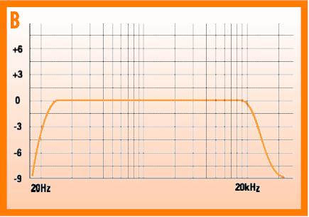
An ideal frequency response would be similar to that claimed for a modern stereo amp:

Click the image to open in full size.

However, the actual process of recording would imprint its own frequency response 'fingerprint' or bias. Thus a magnetic phono record response curve might look more like this:

Click the image to open in full size.

That is, in the process of recording, the final product (a vinyl record and playback needle) has very loud treble, and very little bass.

As a result, the signal needs heavy correction or 'equalization' to restore the sound back to how it originally sounded. Thus the "equalizer" was originally a correction device in the playback chain to compensate for frequency response distortion in the recording and playback media chain.

The "Equalization" is imposed in the preamp stage, just after the signal is retrieved from the record through the magnetic cartridge. Like an adjustable tone control, this circuit imposes its own curve on the signal:

Click the image to open in full size.

The two filtering processes (recording and playback) are supposed to cancel each other out, restoring the signal to its original balance, and achieving a more or less flat frequency response overall.

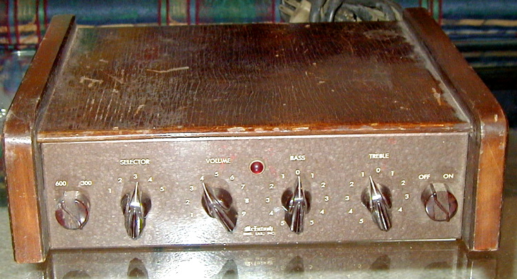
As a matter of history, early attempts at equalization had some variations, before some semblance of standardization sorted itself out in the marketplace, and in the interim, several hi-fi equipment makers offered alternate settings to more closely accommodate various recordings the methods used. The McIntosh AE-2 (pre)amplifier Equalizer control (1950) for instance offered both a 5-position switch and bass and treble adjustments:

Click the image to open in full size.


Today, an RIAA equalization circuit is usually a simplified version (a compromise) of the various EQ curves and standards floating about in the 50s and 60s. It is assumed that most stereo systems will have some kind of 'fine tuning' tone-control adjustments, so that specialized RIAA circuits for each case are not really needed.

Those who are serious about playing back their vinyl records as they were really intended, and with the best fidelity however, will not be satisfied with such commercial compromises, and will want to have a selection of RIAA equalization circuits at hand for playing various records.

In terms of the variations, the following main cases are:

(1) the Columbia 78 rpm circuit

(2) the Columbia 33.3

(3) the RCA Victor 78 and 45 rpm,

(4) the RCA Victor 33.3, and Concert Hall 78 versions.

(4) the London (records) FFRR and Decca FFRR.

These are the most used and most popular versions.

If you have a swelling vinyl collection, it might be wise to do some sorting or labeling on the basis of the RIAA type or equalization needed.
The brand-names and dating will go a long way toward sorting out the issues.

Friday, June 22, 2012

RIAA Preamp Build (Part 1)

Well, someone asked me to design a low-noise stereo preamp for RIAA, (record phono input Equalization), so Challenge Accepted!

I made a preliminary design effort using a Mu-Follower type layout for dead-quiet PSRR and low noise, and also chose a low-voltage tube.  I will be using either 6922s or a 6GM8.

Decided on separate power supply and preamp chassis, for even lower noise, because this is a really low-voltage input signal (old magnetic cartridges etc.).

I enlisted the boy to help me with the power supply.  I took a standard but nice-looking metal box as a base.

The boy loves these special wire-strippers.  He thinks they look like Oscar the Grouch, and calls them the "Eyebrow tool":


I happened to have a ready-made 60 volt filtered supply PCB, loaded and tested. All that was needed was a 12 vAC transformer.  Well, I ordered one on Ebay (notice it says right on it TRANSFORMER).  I assumed the housing was just shielding and a convenient mounting.  This turned out not to be a transformer at all, but a DC power supply containing a transformer!  Who knew!  Idiots.


Well, pressing on, I got some four-wire shielded cable and attached a nice solid connector to it.  This will go to the preamp chassis proper.   I improved the HV insulation inside the plug by weaving electrical tape between the pins.


For tagging purposes, (and additional isolation), I re-paired (no pun) the wires so that the heater (which doesn't matter is two whites, and the HV (60v) is blue/orange (-/+).  Keeps things simple to hook up correctly.


Here's a sneak preview of the other half of the project: My part collection for the preamp itself.  I'm using this nice knick knack box as a base, it looks really nice.  It will have two tubes on it, and some RCA jacks, and a pwr connector.


Not a lot to remark on schematic-wise so far.  Will discuss circuits in following posts.