All about Tubes, Tube Circuits, Tube Gear
Showing posts with label Ultralinear. Show all posts

Monday, June 18, 2012

Ultralinear Guitar Amp (10): Transformers, Grommet!


Transformers, Grommet!


 Yes, whenever you mount transformers to a chassis, always have plenty of rubber grommets to protect the wiring insulation from abrasion, cuts, and short-circuiting!  Especially with high voltage stuff.


First Transformer goes on the Chassis!  Output tranny at one end, and power supply trannies and chokes at the other.  Orientation aint so critical with this incredibly long chassis.


 I always seem to be short of lock-washers.  Ideally locknuts would be even better, but hey, we'll be using what is on hand for this economy build.  When you run out of washers, you can always use nail-polish to fix nuts from loosening, that are never supposed to come off again.  Transformers are one of those parts that should never die!


The second (Power/HV) Tranny goes in the corner.
Here my son is drilling the holes for the massive choke (larger than the Power Tranny!).  We had to check for clearance with the speakers in the Fender cab.


After this quick training exercise, my son is now a professional Grommeter!
It first seems impossible to stuff correct-size grommets into the hole, And in the past I've even cut them to assist in tucking them in.  But the best tool for this is simply a medium flat-head screwdriver.  You have to watch it, so that the rubber isn't penetrated or torn, since that defeats the whole (hole) purpose of protecting the wires from contact with sharp metal edges, and also providing electrical insulation.


Power Plug Innovations:

Next we want to get the power chord installed.  But here, instead of the usual fixed line, we want the new 'computer-plug' style.  There are several good reasons to go this route:

(1)  If the chord is damaged, its an easy replacement, without tools!

(2)  You can change the length of the power cord, if you want to add a longer one!

(3)  There is built-in powerline filtering in most of these units, which is pretty essential these days with tons of digital broadcast noise all around, (cells, internet etc.) and all kinds of equipment piggy-backing on powerlines (local transmission of security, LANS, even audio!).


 But alas, there's a snag!  How do you cut a square/rectangular hole with ordinary tools?  Sure, of course you can make four or more holes with your drill, dig out the jigsaw and cut out the extra metal, and finish up with some various sized metal files; all a lot of annoying and boring work, which is also time-consuming.

Or you can graduate to

The Nibbler!

When I found out about this tool, I fell in love!   It does just what they call it, It nibbles out sheetmetal of almost any thickness or type, and its easy and fast.
Of course the metal handle isn't the most comfortable, but you can either wear a glove, tape on some rubber padding or apply insulating sheaths from a pair of pliers, or just MAN UP and cut the hole!  Usually for one or two holes, you don't need to do much except mark out the size and nibble away!


To get started, you just drill a 3/8" or larger pilot hole to work the tool in to where it can start chopping.  Be sure to use cutting oil to protect the sharpness of your Nibbler tool, which is going to become your favorite tool for cutting perfect rectangular shapes, refitting new parts which are the wrong size, etc.


Here the son gets an instructional hands-on in Nibbling 101.   Soon the AC socket will be ready for power!


A final nostalgic look at today's accomplishments.  Time to rest.
I don't want to tucker the boy out.


A few more internals, like caps, a bridge and a power-switch and fuse, and we'll be ready to wire up and test the output stage!

For that, all we need is a good tube-pedal (like one we built earlier) to drive the splitter, Output stage and transformer!   Lets rock!


Thursday, June 14, 2012

Ultralinear Guitar Amp (9): Tube Holes!


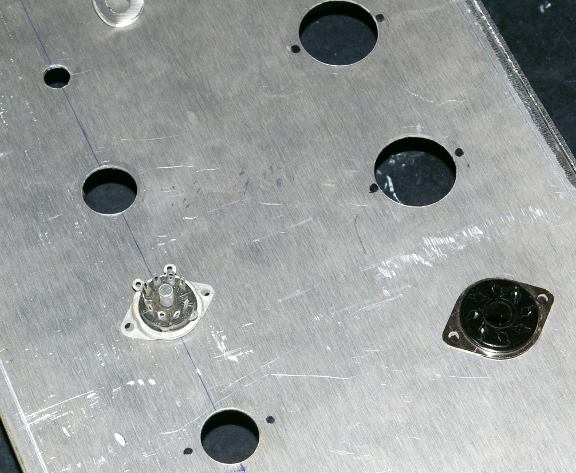
Starting to prep the Chassis!

Here's the latest pics of the build:


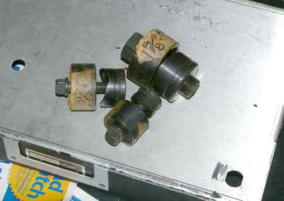
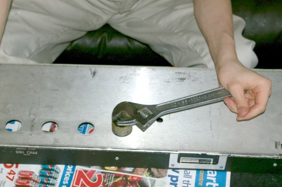
These hole-punches are a lifesaver.
They pay for themselves with their first use.
Make sure you use cutting-oil and regular oil on the threads, to keep them sharp.


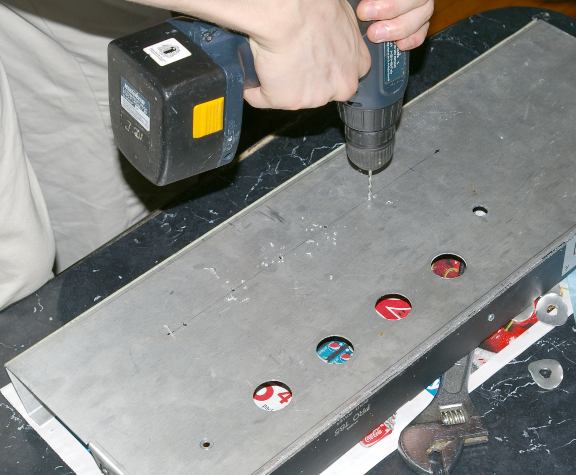
For accurate hole-placement, small pilot-holes are drilled, then a 3/8" hole for the bolt of the hole-punch.
A half-dozen turns and the piece snaps out, leaving a perfect, finished hole.


Even if this project is a flop, nothing beats watching the son actually perform useful work!
- and he's gained experience with a new tool, the hole-punch.


Holes for the mounting bolts are also marked and drilled.


Really nothing should be mounted until the transformers are drilled and bolted on,
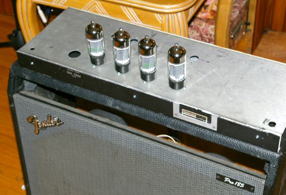
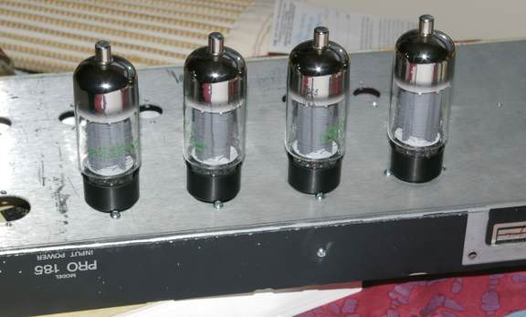
but its hard to resist the fun of pre-assembly and a first look:


Ultralinear Guitar Amp (8): Chassis Prep (cont.)

Nothing like actually getting down to business!

The chassis needed one more modification.
The extra long back was sawed off, leaving about an inch;


The extra piece was also sawed short, to match the height;

This piece has the bend and chassis-bolt nuts which take the back bolts from above.


The piece is bolted to the rest of the chassis, to give a strong,
level surface for mounting the transformers and tubes.

As a result, new holes will have to be drilled in sides of the wooden Fender cab, to line up with the side-bolts.

Good news is, most of the front panel can be re-used, the old way,
with chassis-mounted knobs and point-to-point, using a turret board.


Here's a closeup of the Boltec 100watt UL transformer, with painted bells.
The 'burnt look' was created with a crackle-paint, sprayed lightly over the white.
It gives a hint of the mayhem to come from this best guitar-amp ever built (tribute).


Now the fun begins! LAYOUT Time!


Nothing like a new amp project to get you all fired up!

Click the image to open in full size.

Remember kids! Play Safe!

Click the image to open in full size.

Ultralinear Guitar Amp (7): Chassis Setup

because they are hanging upside down.

First these ones, which grip the base:

Click the image to open in full size.

Then these ones, to hold those babies in regardless of roady mishaps.

Click the image to open in full size.

I know: You're saying, "Why both?"

Because I don't trust either method.

Of course this brings to mind the train scene in Once Upon a Time in the West.

Frank: "How can you trust a man who wears both a belt and suspenders? The man can't even trust his own pants. "


My only misgivings are the potential for shorts/arcing from metal retainer to topcap clip/plate (with 6BG6As).
I may have to use an additional silicon (for heat resistance) insulating ring with a ridge.

Okay, starting to get down to business:

I have stripped the original Fender Transistor Twin chassis,
and spent a week toying with the idea of taking it to a school shop,
and using their bender to fix it up.
Then I just spent ten minutes with a 2x4 and my body weight,
bending it myself on the floor. Not bad.
Now the chassis platform is horizontal,
and the front piece bent at an appropriate angle.
I have yet to saw the over-tall back piece off and re-bolt it,
so that the top-screw lugs line up with the holes in the cabinet.


On the left (chassis) is the Boldec 100 watt Ultralinear transformer.
The bells were painted white and fired for coolness (wasted now inside Fender cab).
On the right (chassis) is the HV tranny and the giant (10 H?) choke (bigger than tranny!).
I got this choke I think from Antique Audio 20 years ago as army surplus.


But I thought the only way to get the son started (and off videogames),
was to dump it on his bench, and make a lot of noise.

I built a bench for him under his bed-loft, (see pic),
to encourage him to learn some electronics before his dad goes senile.


He inherits a lot of cool bits, like that classic EICO oscilloscope,
and custom test-jigs for tube circuits (see upper left).

Some might recognize the ancient Heathkit tone-generator at top right,
and the quickly obsceletized "Distortion Meter" beside it (heh heh).

Ultralinear Guitar Amp (6): Fender SS Twin Box!

Thank God that Fender makes crappy amps!

Turning to the physical construction problem,
I have solved this by the simple expedient of buying a piece of crap.

The Fender Pro 185 is admittedly a loud amp.
Unfortunately, its 'sound' is crudely synthesized by transistor/op-amp technology.

Typically, these amps (like all amps) develop problems like crunchy, noisey volume/tone pots, and crackly cutting-out symptoms, which are notoriously difficult to hunt down and/or permanently fix.

So, such amps have the double-strike that they are both NOT TUBE AMPS, and they have as many or more problems as tube amps.

As a result, their resale value is similar to that of an old foreign car, which offers expensive repair bills and little else.

Yet, for the savvy amp-builder, these boxes have one redeeming feature:
They are about the same in construction as a good Fender Twin Reverb (Tube version).

Obviously, the speakers, having to handle the same power, are the same, and so is the cabinet. To buy these parts individually would be cost-prohibitive, and to build a cabinet, while a worthwhile project on its own for a woodworker, is as expensive as just cannibalizing one.

So I picked up such a crappy amp used, for under $200.
Speaker and Cabinet problem solved:


These speakers are just about the best I could get,
because they are even better than typical Marshalls.
They are designed for abuse, and don't require mounting
in a sealed cabinet, but can handle pretty severe excursions,
and a lot of wattage.


The equivalent 140 watt Fender cabinet without amp would run about $500 new!

But the additional bonus is of course a virtually clean chassis,
with all the mounting parts and re-useable hardware,
e.g., A.C. cable, On switch, silkscreened frontplate etc. etc.


This is another good reason not to sneer at crappy old amps,
that would cost an arm and a leg to fix:
They are natural part-sources.

I may have to cut back or rebend/fold the chassis,
but that is a small price to pay for securing a solid,
practical platform for my amp project.

This was a case of money well spent on this project.

Ultralinear Guitar Amp (5): Output Loadlines

Okay, so now its time to take a good look at the output section expectations:


The Load Line is an interesting problem, and opens a whole pile of questions.

I'll be talking about this for a few posts.
In the diagram above, we have the usual 6L6 curve family, where we are supposed to draw a load line.

Trouble is, the output stage doesn't have a resistive load, so the normal facts don't apply.

With an ordinary resistor load, the tube acts like a variable voltage divider,
and naturally, we can draw a load line by taking the extreme points:

(1) Tube off - complete current shut down (resistance = infinity): now the full power-supply voltage appears across the tube (sort of). Since there is no current, there is no voltage drop across the plate resistor, and the full B+ is at the plate (to ground). This is where the tube goes into "Class AB/B" and turns off for part of a cycle with a big signal swing. The danger at this point is arcing inside the tube, or surface traces/flashes across the pins/socket, if the voltage is too high. or the sockets are dirty or the air is too humid.

(2) Tube full on - minimal resistance, maximum current (resistance = remaining load): now there is no significant voltage across the tube, and most of the voltage appears across the resistor load. For a tube with a plate-load, the plate reads zero volts relative to ground, and the voltage drop across the resistor is the full voltage (minus any voltage drop across a cathode resistor in series with both the tube and load). The danger here is overloading thin wires (usually the grids) with too much current, red heat, meltdown, and tube death. Another potential danger is tube wear: cathode-stripping from over-current and over-heating. Nonetheless even when fully conducting, there isn't really a full short-circuit, since the resistive load (and any cathode resistor) is still in series with the B+


These two extremes serve to provide end-points for a load line, drawn as above (from highest voltage across tube /no current over to lowest voltage / max current). The tube voltage and current is assumed to follow Ohm's Law (a straight line on the chart between the points).

Normally, we would pick an appropriate HV (B+) which fixes one end of the load line,
and then pick an appropriate load impedance (Z-primary) that nails the other end down.
However, we already have a power transformer (fixing choices of B+),
and an output transformer (fixing maximum current and the angle of the load line).

The only question remaining, is where the tube will 'idle' (i..e, its quiescent current), that is, what resistance will it present, and what current will be flowing through it when there is no other signal on the control grid (g1) other than the DC Bias voltage. This idle point is what WE get to set, by picking an appropriate Bias voltage.

We do it by picking an appropriate mid-point on our line, and a modest idle current, then reading (or estimating) what the BIAS voltage will have to be to hold the tube there.

For Class A (full operation) usually we want a good (equal) swing in both directions that stays in safe range and keeps the heat dissipation below the maximum ratings.

The same basic procedure is used for pentode, Ultralinear or Triode modes.
But with pentodes, we want the load angle to avoid dipping into the 'elbow'
and with triode modes we want to follow more conservative ratings and watch screen current, but its the same idea.

In our amplifier, we can't actually pick our own load line, because we already have the transformer, which is fixed at a supposedly 5k ohm impedance.
We can still pick an 'idle' point however, just as with a car we can't change the horsepower or torque, but we can adjust the 'idle RPM' to save gas but keep from stalling.


Looking at the 'load line' here again,
you'll notice I have highlighted the bottom right corner.

Here is where, if the grid was driven far enough, we would cross
the 500 volt barrier, and find the full voltage bearing down on the tube.

Now a 5881 is only rated at 400-450 volts,
and even our tube of choice, the big 6L6GC, is rated at 500 max.

We dropped about 50 volts across the 1.3k cathode resistor
we plan to use for self-bias. This significantly lowers the voltage across the tube,
as long as it is conducting current
(Class A/AB).
This seems to offer enough protection for a 6L6GC (540 - 50 = 490 volts avail.) ...

...and here comes the catch: as long as it is conducting!.

However, as soon as the tubes start shutting down, the voltages again climb too high for safety.

We need to look at why the 6L6GC was rated at 500 volts in the first place:
People were getting shocked trying to change tubes with a top plate-cap carrying 500-800 volts,
and makers (tube makers too) wanted to reduce risk and liability,
so tubes without plate-caps and designed to run on lower voltages were promoted.

Moving the plate-cap to the base however, made higher voltages unreliable,
because of arcing and tracing at the socket
(and arcing inside the tube with smaller gaps between elements inside the tubes!).


We can overcome this problem by (you guessed it!)
reverting back to top-cap plate connections, namely using a
6BG6A instead of a 6L6 as our tube of choice.

Click the image to open in full size.

As it turns out, the 6BG6A is a Higher Voltage version of a 6L6,
like the 807 and 1625 tubes (only more modern).
And its a hell of a lot cheaper than good 6L6GC tubes too!

I happened to pick up a box of them for a few dollars apiece.

With proper HV wire and caps, and a safety-screen to keep idiot-fingers
out of harm's way, this seems like the ultimate solution.

Even if we could squeak a 6L6GC in our circuit using self-bias,
at lower risk, the 5881 would be right out, at a max of 400 volts.

We will test the amp with the 6BG6s, then look into making some options
for retrofitting 6L6GCs or 5881s in a pinch.

The 807 and 1625 would do equally well electrically,
however, we'd also have to invest in special 5-pin or 7-pin sockets (expensive),
which are also unsuitable for tube-substitution or swap-outs.

..so anyway, to recap (no pun intended),

We're going for 6BG6As instead of 6L6GCs.
The basic curves stay the same, but the maximum voltage ratings are increased, allowing "class B" operation,
or excursion into current cutoff as the driving signal crosses over between output tubes (or pairs!).

But we still have some problems with the 'load line':
 

Although we treat the reactive transformer and speaker-load as if it were a resistive load for purposes of drawing the load line,
the premise is basically false, and the real tube behavior will be nowhere near what the load-line suggests:

(1) Suppose we pick an idle-point of 50 mA, which would require a bias of 50 volts, and according to the load-line would leave 300 volts on the plate (dropping a vertical down to the x-axis).

(2) Of course we all should know that the transformer is not a resistor, but only a 'nominal A.C. impedance' of 5k. Its actual (measured) resistance is only 50 ohms per side (on mine anyway).
This means that with 50 mA coursing through it on idle with no AC signal, its only dropping about 2.5 volts, leaving 538.5 volts from ground on the plate! Of course, our self-bias cathode resistor takes up about 67 volts (at 1350 ohms), leaving 471 volts from cathode to plate. Thats safe (while idling) for a 6L6, but not a 5881.

(3) All this suggests that any AC signal at the plate is really riding on a 471 volt D.C. offset voltage (relative to the cathode), and we should really shove our load line over to the right about 171 volts! (or move the scale 171 volts to the left).

(4) A 50v +-, or 100v Peak to peak input voltage, on one tube grid would swing the voltage at the plate about 360 volts, or from 290 to 650 volts + relative to the cathode. Only the 6BG6A will be able to handle that kind of spread.

Ultralinear Guitar Amp (4): Screen Resistors

In regard to screen resistors,
I've read a lot of internet discussions on it,
and some of them actually had some 'meat', i.e., somebody actually tried different values in a commercial amp or two.

What I read left me with this impression:

(1) Although higher resistors limited screen current, something happened to the guitar 'sound'. SR values higher than 600 ohms made the output stage "too stiff", harsh and non-musical in the judgment of the players.

(2) This was thought at first to be some kind of distortion, but turned out to be the opposite! Specifically, the 'attack' was too sharp, possibly reproducing the dismal performance of the pickups or previous stages. No clear results could be given in regard to the 'decay' of a note, but since that was less important it was less noticable.

(3) The cure was to go back to lower screen resistors, to preserve a 'softer' attack, but then make some other adjustment (presumably fixed bias adjustments or lower B+) to protect or enhance tube life.

I was really interested to find out that this approach (increasing screen resistors) was effective from an engineering standpoint but was disastrous musically.

Another case of solving a problem without regard to the overview and/or preserving some desirable flaw.

Ultralinear Guitar Amp (3): 'Blocking Distortion'

Quote:
Originally Posted by DF96 View Post
Under normal circumstances the grid input impedance is high, so the circuit behaviour is determined by the output impedance of the previous stage and the grid bias resistor. When overdriving causes grid current to flow the only resistance is the previous stage o/p Z in series with the grid stopper. Unless the grid stopper is large this circuit can charge the coupling cap quite quickly but it then has to discharge slowly through the grid resistor. If you want to avoid blocking you need a small grid resistor and a large grid stopper, so the time constant hardly changes as grid current flows. This would cause the voltage attenuation you describe, so is not usually done.

If NFB is present the situation can get more complicated because the previous stage might cutoff, so its output impedance shoots up to just the anode resistor value. This might help, because it augments the grid stopper during clipping.

If you want to avoid blocking, then either avoid overdriving or use a proper AB2 driving arrangement.
This is the most clear and succinct explanation so far.

But I have some issues with the analysis:

(1) The current is literally flowing out of the tube when there is grid current. It can go in TWO directions: into the input Cap (at least momentarily, or for a time), and into ground (or into the Negative BIAS supply circuit.

(2) Thus the previous stage Zout is not the 'only resistance'.

(3) Apparently the ability to charge the input Cap without the complimentary ability to discharge it is what you and others have been referring to as "blocking" or "blocking effect/distortion". Like a stuffed up nose, current is stifled, and resistance rises rapidly.

(4) This is only relevant if one has a blocking cap (normally to keep out DC from the previous stage). It may be a better argument for direct or resistive coupling than against class AB/B operation.

(5) the "solution" of increasing the grid-stopper resistance as a 'cure' does appear ridiculous, and frequency-dependent too.

(6) As grid current is diverted into ground instead of back into the previous stage (now blocked by a full cap), the stability of the time constant seems irrelevant, because current flowing through the grid-leak resistor to ground drastically alters the BIAS, causing a potential runaway condition.

(7) When such loss of control over the current flow occurs, even loss of driver voltage becomes irrelevant as well.

(8) I think its "not usually done" for more serious reasons than mere drive-signal attenuation.

(9) The advice to avoid overdriving (i.e., crossing the 0-bias line) or redesign the circuit is great advice, but the steps need explicit expression.

(10) I would guess that both control-loss, undesirable current and voltage changes, and runaway tubes would make proper driver/output stage interfaces mandatory.


Ultralinear Guitar Amp (2): Grid Stoppers

(a) Grid Stoppers: (1.5k - 5.6k ohm range?) I'd like advice on these, I'm not worried about losing a bit of signal, but would rather have stability and immunity from RF...

Reading over the thread on tube tracer building, I was impressed by the fact that even in what seems like simple stable circuits, tubes were still prone to oscillation and excitation, so much so that relatively frequently the tube tester lads were adding resistors to prevent it.

This seems to underline the idea that Grid Stoppers are not merely 'just in case' options, but necessary circuit elements.

Especially when later users are likely to experiment with substituted tubes, a choice of grid stopper that allows the amp to behave under a variety of conditions seems like a good design goal.

In my mind, one can't solve every possible event, but if I limit the list of possible output tubes down to a reasonable subset for this topology and voltage range, I get this:

(1) 6BG6 (first choice).

(2) 6L6GC (2nd choice).

(3) EL34 (not a preference, but a likely experiment to beware of)

(4) 5881 (this is where it gets iffy, because of lower voltage ratings).

I think I may place a sticker inside warning future users not to try lower voltage "6L6"s or 6V6s. But the EL34 should actually work, PROVIDING I prevent too much screen current from flowing. So here is a case where even though I don't like EL34s, it would be smart to design with their possible use in mind.

In the case of the 5881s, switching in some kind of B+ voltage drop option might be workable (a "5881" switch of some kind).
I think I might need some help on that idea, but it can wait.

Now, the grid stopper choice doesn't seem to be too critical, although one thing comes to mind:

Even a low value grid stopper might start eating up driver-voltage if there is grid current happening when the amp is pushed. So it looks like the choice should be as low a value as possible, given the range of tubes contemplated.

What IS critical here then, is to choose a value that doesn't choke off driver voltage to the grids, while still effectively preventing RF/oscillation and instability.

The first thing I am looking at is what other people have done.

MARSHALL: I don't think early Marshalls were well-designed, and even though they may have some 'vintage' sound, I don't think their choice of grid-stoppers will be particularly credible.
Nonetheless, the JCM800s, which use EL34s (6CA7), all have 1.5k grid stoppers.

FENDER:
Here I think there might be something to note. I see in the Fender Twin 100w that for 5881s they apparently shared 1.5k grid stoppers (one for two tubes on each side = 750 ohms/tube? ). Still that is not the tube of choice.

TRAYNOR: This Canadian amp co. presents some unusually conservative and reliable designs, so its worth looking at.

On the 1966 YVM1 Voicemaster they added 10K grid stoppers for 7027 tubes (although many people seem to have substituted EL34s in these old Traynors). This seems unusually high...

The YBA1A Bass-Master Mk2 (1971) has added 1.5k grid stoppers, probably following FENDER designs, and accommodating USA-made 6CA7s (high power EL34s).
Still, some designs leave out grid-stoppers entirely, right up to 1970 revisions, such as the YBA-3 Custom (4x 6CA7s).


HIWATT:
Seem to have put original thought/experiment into grid stoppers; they have 22k grid stoppers in their 4xEL34 output stage (200w).

MESABOOGIE: they use 220 ohm grid stoppers on their Musicman GP-3, with (EL34?)6CA7s, but they are also using opamp drivers....
Their 1972 OrangeAmp MkII however uses 2.4k grid-stoppers on 4xEL34s.

The VOX AC-100 again deviates, with 47k grid-stoppers on only two of the 4 EL34s (not shared!).

Looks like some plagarism in design, perhaps following tube-maker guidelines rather blindly, accompanied by a few maverick experiments, but little consistency or clarity in design constraints...

Anybody have any experience in this aspect of design?

The high values may not be good design choices, (stability problems may be better solved with different methods) , and other variants may be to save on parts, rather than provide 'best design' examples.

If part of the goal was to limit grid current in class AB/B modes, there might be more effective ways of doing that without sacrificing driver voltage.
 -------------------------

Alvis:  "OK, then pick your tube, calculate the resistor based on your specific tubes miller effect.

General questions get general answers.

Weather or not the RF cutoff is at 15Khz or 20Khz is a matter of semantics, both filter out the RF and let the highest guitar frequencies through, hence the range of resistors.

Sometimes its nice to have elbow room, a "range" might allow for different tubes types while still doing the job.

The effect on audio attenuation is very minimal.

Grid Stopper Resistor Calculator
Blocking Distortion

 ----------------------------------

 Just for contrast, it might be good to look at a few older solid designs:

The Western Electric Model 142A (6L6s) uses only a 100 ohm grid stopper! Such classic designers tended to deal with parasitic RF directly using other methods, rather than choke out driver voltages.

On the other hand, one RCA design (mi9377) sports 47k grid stoppers on a 4x 6L6-G design (lower voltages). This seems rather large, especially when we also see regulated screens and RC networks on both halves of the output xformer primary.
Looks like a lot of effort went into bullet-proofing this design, but maybe a better layout would have accomplished more!

The Natural Horizon 20 uses a mere 470 ohms per 6L6G tube in a 30 watt design.

Someone felt it necessary to place 5 ohm resistors on the cathodes of a dual 807 design (high power version of a 6L6).

We see a relatively high value (22k) in Bogen's DO-30A (KT66 pentode mode)

The model A-30 Circlotron gets by with 120 ohm grid stoppers, on its 6BG6Gs.

A 2005 design by Wes Kinsier doesn't use any at all, apparently with good results...

An Ultralinear design from the 1990s using 6CA7s uses only 100 ohms of grid-stopper (and a 10 ohm common cathode as per Hafler's recommendations).

DuKane's 1A475C (100w) with 4x 6CD6GAs uses 10k grid-stoppers only on the second pair.

The "Lil Tiger" mod by Forrest Cook stuffs in 1k grid stoppers on its 6BQ5s.

The Altec Lansing A-340A (2x 6550s) also skips them entirely, preferring instead to invest in a regulated screen supply and a multistage FB loop.

The Maestro (1951) has none on its 6145 outputs.

Gotham's PFB-150WA avoids grid stoppers in its 811A triode design.

No grid-stoppers are to be seen in Altec Lansing's 1570B, which sports a pair of 811As.

Yet another RCA (MI-12246) has none on its 811As.

The Altec Lansing 260A uses only 100 ohm grid stoppers on a pair of 813s, with a thousand watts and dangerously high voltages.


As a trend, older amps have lower value grid stoppers, or none at all.

Is this development an evolution to compensate for an RF polluted environment?
Report Post   Reply With Quote

Ultralinear Guitar Amp (1): Tubes - 6L6GC/6BG6


I am putting together a guitar amp, and hoping for about 40 watts RMS.

I chose 6L6GC as the robust tube of choice (I hate EL34s, especially newer unreliable crap), and am aware of bad tube-eating designs of the past.

I am limited by what I have on hand:

(1) a good Ultralinear 100w Output tranny (5K Zprimary).
This will allow me to expand power later if I can beef up the powersupply (see below).

(2) a nice 300-0-300 HV power tranny,
with a 5 and 6.3v winding. This is underpowered, but I hope to squeeze more out of it by leaving the 5v winding unused, and not overloading the 6.3v winding. I tested these windings with loads, and found:

600v c.t. @ 160 mA (from a load test)
5v rect. heater @ 2A
6.3v main heater @ 4A (before sag)

This doesn't match any current Hammond, but looks like a mix. Its a no-name brand from the 60s or 70s (surplus), possibly JAN.

When I use solid-state diodes, I can wire it full-wave with a 10H choke and a stacked cap giving 100uF (4x 100uF series/parallel 450v), and it looks like I can count on 520 volts under a real load (projecting 4x 6L6 at 40 mA each, push/pull).

(3) 520-540 volts is just a little too much to put on the tubes (even good 6L6GCs), so I'm also opting for self-biasing, so I can drop about 40-50 volts across the cathode resistors). This leaves me at the edge of the design-center max for the 6L6GC, but the low idle current (40mA/tube) will help prevent too much dissipation.

(4) I intend actually to use 6BG6s, which can take 700 volts anyway (topcap plates) without worries. But in a pinch I should be able to put in a set of 2 or 4 6L6GCs made to take 500 volts. I'm going to rig something special to protect the plate caps and people's fingers, and to hold the tubes in regardless of orientation. Also I will probably float the mounting so that the tubes have some shock-insulation, to improve microphonics and protect the tubes from banging.


(5) Ultralinear Topology: I intend to take advantage also of the Ultralinear tappings, so that I can avoid building two extra powersupplies (screen and bias). This should allow lower idle current without undue distortion.

(6) Four Output Tubes:
The idea here is to lighten the current load on each tube, and also drop the internal output impedance of the power stage.

(7) The splitter/ driver circuit is still up in the air. I haven't chosen a topology for this, and wish to hear what others think from their personal experience (comparisons) especially in regard to keeping the output stage balanced as tubes age, with low maintenance, and a good match to provide current to drive the output stage grids, in case they draw current.

(8) Looking at the basic loadline, I find there is a small 'danger' zone at the lower-right, where the voltage across the 6L6s could climb above 500 volts (the design max) as the tube shuts off, if the input signal were driven hard enough to push the stage into class B temporarily... I think I can get a good 40 watts without too high an input voltage, but in any case the 6BG6s will be able to take the overdrive/classB. Its only the 6L6CG scenario that worries me. Any comments would be appreciated. But with self-bias, there is much more headroom, even with the 6L6s.

(9) The 'guitar-amp' sound will be mostly derived from manipulating the input section,
so I would really like to hear what people have to say about good preamp designs re: guitar sustain and harmonic content.

(10) I'd like to have a simple but effective Parametric EQ, something like the EQ in a BOSS MT-2 pedal (bass, mid/Q, treble) only modded for a better choice of frequency ranges. I could use a hand on that, again, I want to use tubes for this (maybe an 12AT7 or two).

Obviously I can do this in stages, as I get the results I need at each step, and move on to the next addition/mod.


Right now, I have on the table the following issues,
and could use some advice:


(a) Grid Stoppers:
(1.5k - 5.6k ohm range?) I'd like advice on these, I'm not worried about losing a bit of signal, but would rather have stability and immunity from RF...

(b) Screen Limiters: (450 - 680 ojm range?) I read a discussion somewhere on here about guitar amps, and the problems with EL34s etc., along with typical values and preferred. But any input or advice would be good, especially as apparently screen current will significantly affect sound as well as tube-life.

(c) Grid-Leak / Input: (100k - 470k? ) with self-bias, I should be able to tolerate values a little higher, but I am more inclined to want the self-bias on the grids to work well, rather than 'maximize' input Z here. Any advice?

(d) Cathode Bias: (500 - 1.5k ohm ?) I found experimentally that to get a good 48-50 volts on the grids and keep the current down to near 40 mA per tube, I needed at least 1.3k cathodes (with Svetlana 6L6GCs).
But the issue doesn't stop there, because I could use one large common cathode resistor per tube-pair (e.g., 650 ohm). However, Hafler found that a 10 ohm common resistor was apparently the right amount of 'common resistor' to minimize intermodulation distortion (presumably the rest of each cathode resistance was separate). Any leads on this would be welcome.
Also whether or not to bypass, as it seems I would trade off lower output impedance (which may be unnecessary with 4 tubes) against the sound degradation that say 47uF electrolytics would introduce....please tell me what you think!

Other issues I need to settle are:

(e) Input isolating caps for input each side (.22uF? 600 v?) of power stage. Since its not a hi-fi, perhaps polystyrene or something not too expensive could go here?

(f) RF inhibitors and stabilizer additions:

Here I'm thinking of an RC series between screen and plate on each side, an RC series across the primary of the output xformer, and also a 100 ohm resistor across the Secondary in case a speaker is unplugged or goes open-circuit.

Any other safety features would be also welcome.
I am going to place an internal fuse between the HV B+ and the output xformer primary c.t., but what else can I do to protect tubes and xformer from spikes due to failure or user-error?