All about Tubes, Tube Circuits, Tube Gear
Showing posts with label Power Amp. Show all posts

Monday, June 18, 2012

Ultralinear Guitar Amp (10): Transformers, Grommet!


Transformers, Grommet!


 Yes, whenever you mount transformers to a chassis, always have plenty of rubber grommets to protect the wiring insulation from abrasion, cuts, and short-circuiting!  Especially with high voltage stuff.


First Transformer goes on the Chassis!  Output tranny at one end, and power supply trannies and chokes at the other.  Orientation aint so critical with this incredibly long chassis.


 I always seem to be short of lock-washers.  Ideally locknuts would be even better, but hey, we'll be using what is on hand for this economy build.  When you run out of washers, you can always use nail-polish to fix nuts from loosening, that are never supposed to come off again.  Transformers are one of those parts that should never die!


The second (Power/HV) Tranny goes in the corner.
Here my son is drilling the holes for the massive choke (larger than the Power Tranny!).  We had to check for clearance with the speakers in the Fender cab.


After this quick training exercise, my son is now a professional Grommeter!
It first seems impossible to stuff correct-size grommets into the hole, And in the past I've even cut them to assist in tucking them in.  But the best tool for this is simply a medium flat-head screwdriver.  You have to watch it, so that the rubber isn't penetrated or torn, since that defeats the whole (hole) purpose of protecting the wires from contact with sharp metal edges, and also providing electrical insulation.


Power Plug Innovations:

Next we want to get the power chord installed.  But here, instead of the usual fixed line, we want the new 'computer-plug' style.  There are several good reasons to go this route:

(1)  If the chord is damaged, its an easy replacement, without tools!

(2)  You can change the length of the power cord, if you want to add a longer one!

(3)  There is built-in powerline filtering in most of these units, which is pretty essential these days with tons of digital broadcast noise all around, (cells, internet etc.) and all kinds of equipment piggy-backing on powerlines (local transmission of security, LANS, even audio!).


 But alas, there's a snag!  How do you cut a square/rectangular hole with ordinary tools?  Sure, of course you can make four or more holes with your drill, dig out the jigsaw and cut out the extra metal, and finish up with some various sized metal files; all a lot of annoying and boring work, which is also time-consuming.

Or you can graduate to

The Nibbler!

When I found out about this tool, I fell in love!   It does just what they call it, It nibbles out sheetmetal of almost any thickness or type, and its easy and fast.
Of course the metal handle isn't the most comfortable, but you can either wear a glove, tape on some rubber padding or apply insulating sheaths from a pair of pliers, or just MAN UP and cut the hole!  Usually for one or two holes, you don't need to do much except mark out the size and nibble away!


To get started, you just drill a 3/8" or larger pilot hole to work the tool in to where it can start chopping.  Be sure to use cutting oil to protect the sharpness of your Nibbler tool, which is going to become your favorite tool for cutting perfect rectangular shapes, refitting new parts which are the wrong size, etc.


Here the son gets an instructional hands-on in Nibbling 101.   Soon the AC socket will be ready for power!


A final nostalgic look at today's accomplishments.  Time to rest.
I don't want to tucker the boy out.


A few more internals, like caps, a bridge and a power-switch and fuse, and we'll be ready to wire up and test the output stage!

For that, all we need is a good tube-pedal (like one we built earlier) to drive the splitter, Output stage and transformer!   Lets rock!


Thursday, June 14, 2012

Ultralinear Guitar Amp (9): Tube Holes!


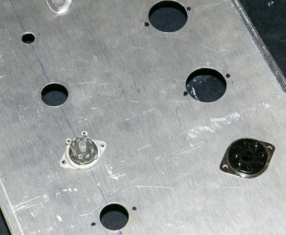
Starting to prep the Chassis!

Here's the latest pics of the build:


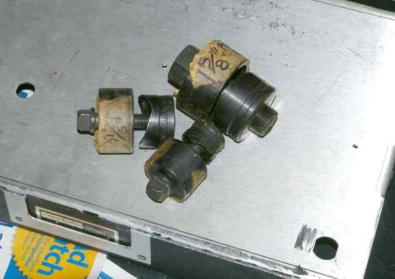
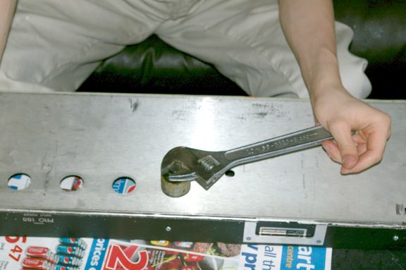
These hole-punches are a lifesaver.
They pay for themselves with their first use.
Make sure you use cutting-oil and regular oil on the threads, to keep them sharp.


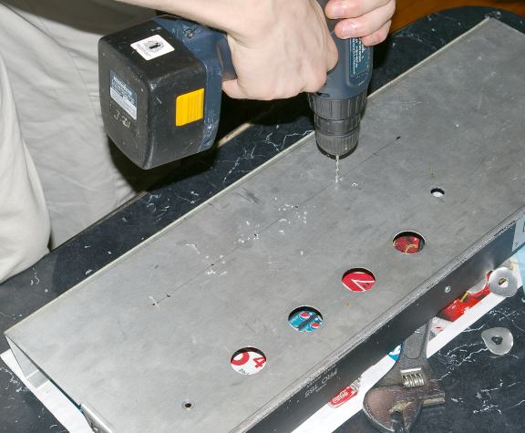
For accurate hole-placement, small pilot-holes are drilled, then a 3/8" hole for the bolt of the hole-punch.
A half-dozen turns and the piece snaps out, leaving a perfect, finished hole.


Even if this project is a flop, nothing beats watching the son actually perform useful work!
- and he's gained experience with a new tool, the hole-punch.


Holes for the mounting bolts are also marked and drilled.


Really nothing should be mounted until the transformers are drilled and bolted on,
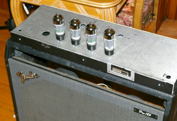
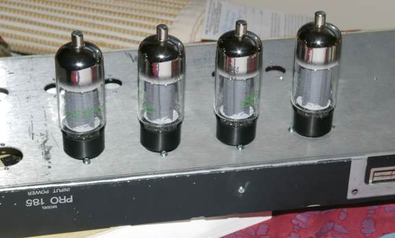
but its hard to resist the fun of pre-assembly and a first look:


Ultralinear Guitar Amp (8): Chassis Prep (cont.)

Nothing like actually getting down to business!

The chassis needed one more modification.
The extra long back was sawed off, leaving about an inch;


The extra piece was also sawed short, to match the height;

This piece has the bend and chassis-bolt nuts which take the back bolts from above.


The piece is bolted to the rest of the chassis, to give a strong,
level surface for mounting the transformers and tubes.

As a result, new holes will have to be drilled in sides of the wooden Fender cab, to line up with the side-bolts.

Good news is, most of the front panel can be re-used, the old way,
with chassis-mounted knobs and point-to-point, using a turret board.


Here's a closeup of the Boltec 100watt UL transformer, with painted bells.
The 'burnt look' was created with a crackle-paint, sprayed lightly over the white.
It gives a hint of the mayhem to come from this best guitar-amp ever built (tribute).


Now the fun begins! LAYOUT Time!


Nothing like a new amp project to get you all fired up!

Click the image to open in full size.

Remember kids! Play Safe!

Click the image to open in full size.

Ultralinear Guitar Amp (4): Screen Resistors

In regard to screen resistors,
I've read a lot of internet discussions on it,
and some of them actually had some 'meat', i.e., somebody actually tried different values in a commercial amp or two.

What I read left me with this impression:

(1) Although higher resistors limited screen current, something happened to the guitar 'sound'. SR values higher than 600 ohms made the output stage "too stiff", harsh and non-musical in the judgment of the players.

(2) This was thought at first to be some kind of distortion, but turned out to be the opposite! Specifically, the 'attack' was too sharp, possibly reproducing the dismal performance of the pickups or previous stages. No clear results could be given in regard to the 'decay' of a note, but since that was less important it was less noticable.

(3) The cure was to go back to lower screen resistors, to preserve a 'softer' attack, but then make some other adjustment (presumably fixed bias adjustments or lower B+) to protect or enhance tube life.

I was really interested to find out that this approach (increasing screen resistors) was effective from an engineering standpoint but was disastrous musically.

Another case of solving a problem without regard to the overview and/or preserving some desirable flaw.

Ultralinear Guitar Amp (3): 'Blocking Distortion'

Quote:
Originally Posted by DF96 View Post
Under normal circumstances the grid input impedance is high, so the circuit behaviour is determined by the output impedance of the previous stage and the grid bias resistor. When overdriving causes grid current to flow the only resistance is the previous stage o/p Z in series with the grid stopper. Unless the grid stopper is large this circuit can charge the coupling cap quite quickly but it then has to discharge slowly through the grid resistor. If you want to avoid blocking you need a small grid resistor and a large grid stopper, so the time constant hardly changes as grid current flows. This would cause the voltage attenuation you describe, so is not usually done.

If NFB is present the situation can get more complicated because the previous stage might cutoff, so its output impedance shoots up to just the anode resistor value. This might help, because it augments the grid stopper during clipping.

If you want to avoid blocking, then either avoid overdriving or use a proper AB2 driving arrangement.
This is the most clear and succinct explanation so far.

But I have some issues with the analysis:

(1) The current is literally flowing out of the tube when there is grid current. It can go in TWO directions: into the input Cap (at least momentarily, or for a time), and into ground (or into the Negative BIAS supply circuit.

(2) Thus the previous stage Zout is not the 'only resistance'.

(3) Apparently the ability to charge the input Cap without the complimentary ability to discharge it is what you and others have been referring to as "blocking" or "blocking effect/distortion". Like a stuffed up nose, current is stifled, and resistance rises rapidly.

(4) This is only relevant if one has a blocking cap (normally to keep out DC from the previous stage). It may be a better argument for direct or resistive coupling than against class AB/B operation.

(5) the "solution" of increasing the grid-stopper resistance as a 'cure' does appear ridiculous, and frequency-dependent too.

(6) As grid current is diverted into ground instead of back into the previous stage (now blocked by a full cap), the stability of the time constant seems irrelevant, because current flowing through the grid-leak resistor to ground drastically alters the BIAS, causing a potential runaway condition.

(7) When such loss of control over the current flow occurs, even loss of driver voltage becomes irrelevant as well.

(8) I think its "not usually done" for more serious reasons than mere drive-signal attenuation.

(9) The advice to avoid overdriving (i.e., crossing the 0-bias line) or redesign the circuit is great advice, but the steps need explicit expression.

(10) I would guess that both control-loss, undesirable current and voltage changes, and runaway tubes would make proper driver/output stage interfaces mandatory.


Wednesday, June 13, 2012

Ju-Jutsu: Ultimate Monoblock (Pt 8) Early Builds


To give a sense of what the physical build was like for this topology, I'm posting some photos of the original prototype for the studio-model we used at the 64 track studio as monitors.

This set of rack-mount monoblocks served also as the breadboard for the finalization of design specs
(and yes, we tried almost every topology including SRPP+ styles, and modifications on the taps, before settling on the Mu-Follower configuration, because of sound quality, the only object in this build)

The Redline Pro Rack-mount Series, serial #002L


We chose rack-mount to integrate these power amps into the studio environment.
This entailed a separately housed powersupply, and heavy-duty cabling to protect sound techs.

The case allowed a quick-hinge to access tubes and do testing.
The amps were fully functional with the cases closed,
but the power tubes (sockets) must be oriented such that grid-sag cannot occur
when running full-tilt. Later versions of the amp reverted to upright positions,
because questions were raised regarding future reliability and standardization of available tubes.


most of the wiring-harnesses below in the prototype were taken in and out multiple times,
so we weren't too concerned about final layout, but only easy point-testing etc.

The configuration shown (6550 / 6L6GC / 12AX7A) was an implementation
which delivered the right amount of power to compete with the MacKintosh's,
which at the time were the hands-down industry standard for mixdown.
Our amp blew the Mackintosh away in both power and clarity, quite a feat at the time,
although we weren't sure just how good our design was, until we A/B'ed it against the Bryston SS power amps, considered the cleanest high-power amps available commercially in the 90s.

here in the side-view, you can see the simple layout for the tube circuits,
consisting of perf-board units mounted close to the tubes.
It is important to realise that the two 12AX7s here are each running at different heater-voltage offsets, about 300 volts apart, and so each partial mini-board is a different set of components (i.e., amplifier and CCS top).


Another view of the simple layout for the power-stage is shown below:


The reason you see some resistors end to end (besides for connecting),
is that standard resistors are only rated for about 300 volts, but in this circuit,
there could be transients 5 times that high. In key positions, after voltage-testing,
we sometimes made up a value by series, doubling the voltage rating, and power handling.

The signal caps were gooped to prevent vibrations in the signal-path.

The inside back panel held both the OT and the input circuitry, as well as a DC cooling fan.
This was added because in the studio environment, the amps were in a separate sealed room,
mounted alongside other devices (amps, board PSs for the Neves etc.).
The noise of the fan was small, and did not intrude into the circuit which was nearly impervious to hum or noise pickup.


The use of the Jensen input transformer allowed a choice of balanced and unbalanced inputs,
allowing flexibility in application in studio situations.


The back of the panel shows the triple-insulated PS cabling, also protected by heat-shrink and cut-resistant plastic fibre tubing, which provides safety in the event of potential cable damage from door slamming, pulling, sharp edges in the rack etc.

All in all, these amps performed well above the Mackintoshes that they replaced,
creating a stunning staging clarity which was very useful for both recording and mixdown sessions.
Most of the engineers were shocked by the imaging,
which however was not always easy to reproduce on cheaper commercial units
which consumers were expected to be playing back the mixes on.

This forced us to use a variety of mixdown tests, so that we were not misled by the great sound,
as to what a mixdown was going to sound like in a real-world home or club environment.
For those purposes, mixdowns were also tested on Cerwin-Vega club gear, and typical home stereo units.
The idea of a 'near-field' standard was not yet solidified in the big studios at that time.

Ju-Jutsu: Ultimate Monoblock (Pt 7) The Amp

Now we can see the Ju-Jutsu Amp (SE Stereo) in its true light and simplicity.
It is simply a pure two-stage amplifier, in real linear operation,
with a pristine DC supply, and no current in the OT.


I've stuck in some LEDs to bias the first stage, as some people might want to try it.

When the Mu-Follower is understood as it really is,
a sophisticated power-supply regulator circuit combined with an ideal load,
we can see plainly how the amp achieves near-perfect distortion-free operation.

The only two caps in the signal path are in the PS chassis.

Ju-Jutsu: Ultimate Monoblock (Pt 6) PSRR


 Lets rearrange the Top Tubes in our amp, and put them on a separate Power-Supply Chassis, with the HV B+.


For SE operation, we have to do a little extra isolating of HV power supply to the top tubes,
using additional Cap/Resistor legs. (top of diagram).

Also, we install the signal caps on the PS chassis, so that at least two of the connecting lines
have no High Voltage DC (this is blocked by the caps.
Even the two lines with DC only have half the full B+ voltage,
since it is divided ('dropped') across the Top Tubes.

You can use ordinary 600 volt insulation wire (shielded) between PS and Amp Chassis.
Make sure you orient any connectors safely (males on receiving circuits, females on power sources).

Although there are now two tubes (a 12AX7 and a 5998 for instance) on the PS chassis,
it really isn't any more than you'd find on almost any regulated HV powersupply.
What has happened is that we have simply made more intelligent use of similar tubes,
with much more spectacular results.
Why have a mere 'regulated' supply, when you can have a 'feedback-controlled' CSS supply?
Don't forget to add a good heavy gauge ground line between the two chassis.


"Nazaroo, I'm not seeing what is the advantage of relocating the upper tubes of the Mu-Follower to the P.S. chasiss. Please clarify. Thanks."
 
(1) It helps isolate the real dangerous high voltage and keep it contained in the powersupply.

(2) Teaching purposes, so that people can understand the true meaning of the Mu-Follower.

(3) The separate heater supply for the top tubes (with HV offset) is also isolated.

The heater supply is perhaps the most dangerous, because even seasoned technicians
forget that it can have lethal HV riding on it.

Ju-Jutsu: Ultimate Monoblock (Pt 4) Output Stage


While we're at it, lets look at the real output stage:


Again we see balanced-input complimentary Mu-Follower circuits,
each providing 1/2 of the P to P voltage across the transformer.
The nice thing is, there is no DC flowing through the OT.
The tubes get their current from the Power Supply through the top tubes,
and the OT route is superfluous.

The blocking cap I used was 10 uF, 600v polyprop, the only expensive cap in the whole amp.
It's also bypassed with a fastcap low esr, just in case.
The cap should not face any voltage other than the output signal.
If there were a slight imbalance between the tubes,
and a small DC voltage difference between the two tapping points,
who cares? its blocked.
The beauty of this is that the tubes don't even have to be balanced, as in a std Push-Pull.
The DC offset can't dump any current into the tranny, so there's no concern at all.
The tubes would have to be woefully out of wack to have any effect on the signal.

Since this is a constant-current style circuit, operating high in Class-A,
there is no question at all of 'blocking-distortion' from grid current in the bottom tubes.
But still the input grid-leak resistors should be as recommended by tube-makers,
e.g., for a 6550 say 100k and an appropriate input cap, say 1 uF.
Again with the Hafler cathode circuit, which minimizes Push-Pull IM.

What can I say?
These output tubes have to be self-biased, because of the huge high voltages across the circuit.
But thats okay, because the Mu-Follower forces linearity on both tubes,
even before they have to cancel out small non-linearities from each other.
Win win again.
Use large wattage cathode resistors, and adequate ventilation.
Don't forget sensible grid-stoppers and screen-grid stoppers on all power pentodes/tetrodes in Triode-mode.
Look at recommendations for the specific tubes you're using.

I left out a 100-200 ohm parallel resistor across the output secondary, to prevent spikes
in case of speaker-failure or disconnection.

The top tube in the WWII model (5998) cannot be substituted with a 6AS7G,
without significant modifications.
Try to put 1/2 to 2/3 of the B+ across the bottom tubes.
If you're using an SE transformer you can try omitting the blocking-cap in the primary!

Again, critically important to have a separate floating or DC-biased heater-supply for the top tubes.
Stay within 100 volts of the cathode, or as per tubesheet recommends.

Not only is any PS noise blocked by the heavy topload Mu Followers,
whatever signal gets through is near-perfectly cancelled across the transformer primary.

Remember that these Output stages are nearly CC,
so whatever small PS noise is left from the voltage-divider action,
is almost always near-perfectly cancelled.

noise free. hear the difference.

Ju-Jutsu: Ultimate Monoblock (Pt 3) First Stage

Okay lets look at the input / stage 1.


Overview:

What is going on here?

First of all, I chose balanced stages all the way through the amp.
We have to get to balanced anyway, for a Push-Pull at the output stage,
so at some point I'd need an interstage transformer or a splitter, with all those problems:
added stages, another layer of distortion etc.
Well I learned a lesson working with professional studio gear, which is balanced all the way from the microphone.
It works best, and gives the highest noise immunity and lowest distortion.
All the advantages of the Push-Pull (harmonic cancellation, Powersupply noise cancellation)
are now transferred to the whole amp.
If the Mu-Follower wasn't clean enough, its now bullet-proof.

What you are looking at is two Mu-followers, one for each side of a balanced input.
One is drawn upside down for symmetry and beauty.
The input transformer is a Jensen.
Simply put they make the best input transformers you can buy.
We use them in everything in a studio environment, for isolation, balance, and frequency-response, noise immunity, and low distortion.
They are a cost-effective solution and replace an interstage transformer, which,
to get the same specs would cost a fortune, and they don't make them like this anyway.
Jensen can make near-perfect transformers because of the signal amplitude and size.
Nuff said. No one in their right mind would prefer an interstage to an input transformer.

That leaves the resistor values.
The input stage here could be any tube, but lets pick a 12AX7A
just to keep it easy to get good quality cheaply available parts.

Well, we'd like about 250 volts across each tube.
We'd like to bias them according to my little method.
But people have designed plenty of 12AX7 Mu-Followers,
and you can use tested circuits that are known to deliver high fidelity.

Some things never change.
The input grid resistor for each triode should be 500k to 1Meg R.
This provides an appropriate input impedance for the transformer,
and a path to ground to (self-)bias the grid.
The cathode resistor should be about 1k R to give a volt or two of self-bias.
It's positive voltage at the top (due to the idle current) makes the grid relatively negative.
Input tubes should pretty much always be self-biased unless you have a good reason not to.
If you are using a 6922 or some other more sensitive tube, don't forget a grid-stopper (shown).
Otherwise you risk hidden parasitic oscillation and poor performance.

You'll notice I have a three-resistor network to ground for the two bottom tubes (one upside-down).
That's Hafler's minimum IM distortion trick, discussed in the literature.
You can just as easily use a couple of LED diodes to ground on the bottom tubes (NOT the top ones!!!),
as some people are doing these days (they weren't available in Hafler's day).

The top tubes are set up similarly, but the extra resistor on the cathode is another parasitics-stopper (horizontal, optional).
Again a 500K resistor (or 1 Meg R) is a grid-leak or input resistor (and a horizontal grid stopper if needed: try 1k).

The top resistor is not really a load resistor, its again a 'parasitics stopper' resistor. (500 R would do, or even skip it).
The top tube is operating as a cathode follower.

The input cap for the top tubes are .22 uF, but you could use a .1 uF, its not critical.
What's left? The input is grounded to the chassis- via a star-ground at the bottom of the input tubes.
This is for shielding, but it can be skipped, and you could just use an XLR input for a balanced line input.
You could even eliminate the input transformer entirely if you have balanced lines.

Any questions? No, then we can move on to the next (last) stage.